Parts of the REMS boom
Parts of the REMS boom
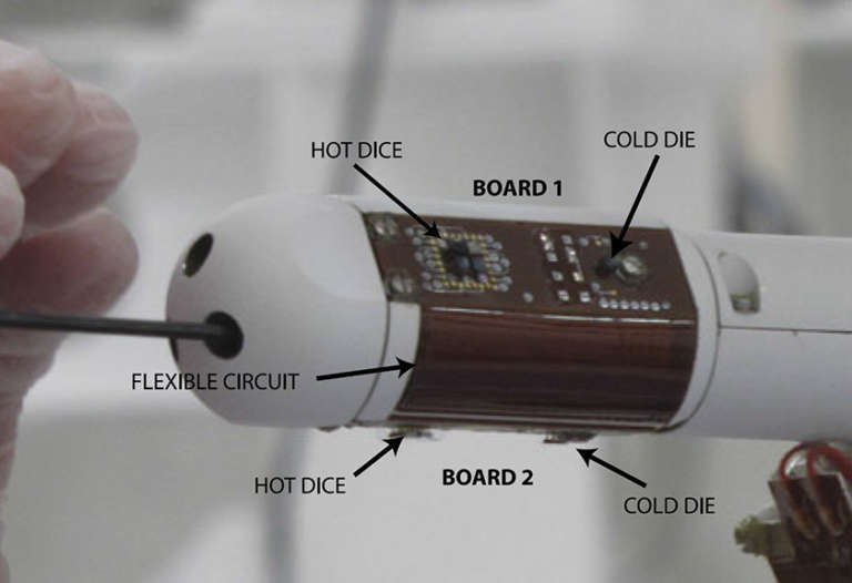
Parts of the REMS boom This image was taken during the REMS integration into the rover, and shows two of the wind sensor boards. Each boom has three identical boards (Boards 1 and 3 on the sides, and 2 on the lower part of th boom). Board 1 and 3 are connected to Board 2 by a flexible circuit and this is connected to the integrated circuit board, in the back of the boom, by another flexible circuit. Each board has four hot dice and one cold die (the four hot dice are in the front of the board and the cold one is in the back). All dice are identical, manufactured in silicon, with three resistors printed on the upper side and thermally isolated from the board by four pillars with a low thermal conductance. In the hot dice, a resistor is used to heat it, another one is used as a sensor to measure the temperature, and the third one is used as reference sensor in the measurement circuit. In the cold die, the only resistor used is the reference resistor. The control loop compares the temperature of the hot dice with that of the cold die, to control the power injected to keep a constant predefined temperature difference (delta temperature) between them. Each board has an additional thermistor on its inside face to monitor the board’s temperature and evaluate the conductive thermal losses of the dice. NASA / JPL / Gomez-Elvira et al.

Here is an (unfortunately teeny) image of the boards and flexible circuits before installation onto a boom, taken from this REMS website.

REMS wind sensor circuit boards