Timothy Reed • Jun 15, 2009
Gravity's Bow
When spacecraft visit other planets, they are armed with an array of instruments; cameras and spectrometers that image and measure ambient light from a distance, laser altimeters that project their own light and receive back distance information, magnetometers to measure the local magnetic field, particle detectors to look for particles of various energies, masses and changes, and the like. My specialty for 20 years has been passive optical systems, primarily the large aperture, high-resolution camera systems that provide, among other things, the "gee-whiz" images that capture the public's attention and imagination.
But most people don't realize the complexities involved in getting images from space. (I talked to someone once who thought that the Hubble Space Telescope takes pictures on film and drops them to the Earth for recovery.) Many people assume that a camera designed to take a picture from space is more or less like their own digital camera, albeit with a big telephoto lens and some extra-special "space enhancements." So Emily asked me to talk about some of the behind-the-scenes details and considerations of sending hardware into space, from an engineer's point of view.
Launching precision optical systems on spacecraft can be a tricky proposition. Imagers work by taking the incoming light from distant objects and directing it onto the pixels of a detector. Anything in the environment of the camera that causes perturbations or misalignments can destroy how the light focuses onto a single pixel. Since high-resolution imagers distinguish between objects that are separated by the tiniest of angles--sometimes on the order of millionths of a degree--very small perturbations in the imager can have a devastating effect on the quality of the image. The higher the resolution of the imager, the more susceptible it is likely to be to perturbations.
Ideally, we'd want to put a highly sensitive system in a very massive and rigid support structure to prevent mechanical perturbations, disturb it very little, and keep it in a temperature controlled environment. Instead we put it on a rocket where it must have as little mass as possible, shake it like mad during launch, and put it in vacuum and zero gravity where it is exposed to severe temperature extremes.
That's why space-bound instruments go through rigorous rounds of testing on vibration tables and thermal vacuum chambers, to verify that they will perform well even after being exposed to these harsh environments.
But there's one environment that engineers must take into account which at first sounds counterintuitive. Gravity.
For large optical systems, the effects of gravity can be a significant and difficult problem to overcome. Although these instruments operate in a zero-gravity environment, they're aligned and tested on Earth. While the mechanical structures that hold the optics in place are designed to be as stiff as possible, it is often impossible given the spacecraft mass constraints to make a structure that doesn't bend slightly under the force of gravity. The resulting gravity sag can be enough that a perfectly aligned and tested system (on Earth) can spring in the opposite direction once in zero-gravity, severely degrading the image.
I've had the chance to employ several techniques to overcome the effects of gravity sag during the build and testing of NICMOS (Near Infrared Camera Multi Object Spectrometer) on board the Hubble Space Telescope, HiRISE (High Resolution Imaging Science Experiment) on board the Mars Reconnaissance Orbiter, the Quickbird and WorldView commercial Earth imagers for DigitalGlobe, and development mirrors for the James Webb Space Telescope. Here's a brief primer on three methods to overcome gravity.
Method 1--Vertical orientation. If the system is symmetrical about the optical axis, gravity sag can be reduced by aligning and testing the system vertically. In the case of the HiRISE imager the primary and secondary mirrors of the telescope are on a straight line. The side-to-side tolerance between these two mirrors is 12 microns--small enough that if the telescope were mounted horizontally, the graphite composite structure of the telescope would sag and deform by more than that amount. The solution was to mount the telescope vertically in an orientation where sag was minimal and to adjust and measure the mirrors in this orientation.

Method 2--Splitting the difference. A telescope structure that sags with gravity when horizontal will deflect a particular amount in one orientation, and an equal but opposite amount when flipped or rolled by 180 degrees. Measuring the sag in each orientation can allow the calculation of the null deflection--the desired zero-gravity alignment. The alignment of the optics can then be set to include this "windage"--intentionally misaligning the telescope by just the right amount such that in zero-gravity the telescope will spring back to its perfect intended alignment. This was used in the final testing of HiRISE when existing test equipment required the optical axis of the telescope to point horizontally. The non-symmetrical design of the QuickBird and WorldView commercial Earth imagers were also excellent candidates for this technique. To properly execute this technique requires the utmost confidence in the accuracy of the analysis--the telescope intentionally performs less than optimally in its final configuration while on the ground. It is only after the system is launched and in zero-gravity that final confirmation of its performance is possible.

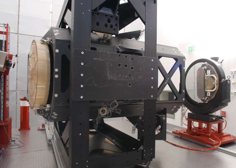

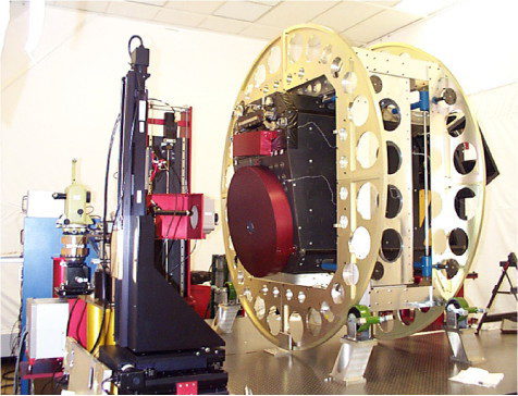
Method 3--Counterweights. In some cases, gravity can be removed in an optical system by the judicious use of offsetting counterweights. Complex lever and counterweight systems are often found in the primary mirrors of the largest terrestrial observatories. I found it necessary to provide a simpler system for the measurement of a technology demonstrator mirror for the James Webb Space Telescope.
This ultra-lightweighted beryllium mirror has a network of ribs as thin as 1 mm on its rear surface. It was being tested in a thermal vacuum chamber at Marshall Space Flight Center in Huntsville, AL and the long focal length of the mirror required that the test be conducted with the mirror's axis horizontal. But the extreme lightweighting of the mirror caused the surface to sag under its own weight, deforming it unacceptably. A system of balance lever arms and counterweights was employed to counteract the effects of gravity. The design of the counterweight system was complicated by the fact it had to operate properly when the system was being tested at a cryogenic temperature of 35K!

There are many more ways that ingenious and dedicated engineers tackle challenges like this in the design and construction of optical systems for spaceflight; the result is the amazing precision and resolution that continues to reveal the secrets of the universe, and awe and inspire us with spectacular images from space.
The Time is Now.
As a Planetary Defender, you’re part of our mission to decrease the risk of Earth being hit by an asteroid or comet.
Donate Today

 Explore Worlds
 Find Life
 Defend Earth