Phil Stooke • May 27, 2016
Lunar Farside Landing Plans
I attended the Lunar and Planetary Science Conference, better known as LPSC, in March this year, and then spent an enjoyable few days in Flagstaff, Arizona. It was quite a change going from the warmth of a Houston spring to snow on the ground in Flagstaff, but we have to take what nature dishes out in the pursuit of science.
Actually, it wasn’t really science I was pursuing, but rather the history of science, and of space exploration. When I was last in Flagstaff, in 2003, I was looking for Surveyor images to prepare panoramas for my International Atlas of Lunar Exploration, and for some things deposited in the Branch History Collection by Don Wilhelms, the author of To a Rocky Moon, one of the best books there is on the science of Apollo. Don worked on landing site selection for Apollo, among other tasks, at the United States Geological Survey (USGS) in Menlo Park. He deposited many of his collected papers, including committee minutes and other materials, in Flagstaff. Adrienne Wasserman, then head of the Regional Planetary Image Facility, helped me find what I needed, but two binders of Don’s materials concerning Apollo 17 site planning were missing. They had been borrowed by none other than Jack Schmitt, the Apollo 17 astronaut, and I couldn’t wait for them to be returned, so their contents never made it into my Atlas.
But now it’s 2016, my book is ten years old, and it needs revising and updating. So, I went back to Flagstaff to look for those items and anything else serendipity might offer me. Astrogeology at USGS is housed in the Shoemaker Building up on a hill above the town, with a great view of the mountains. The first thing I saw inside the building was Grover, not the Sesame Street character but a test model of the Apollo Lunar Roving Vehicle which was used by the astronauts to train for the later landings. Grover is more robust than the real LRV was, to cope with Earth gravity. I was happy to see it because in 2003 it had been ‘borrowed’ by NASA HQ and some people thought they would never see it again.
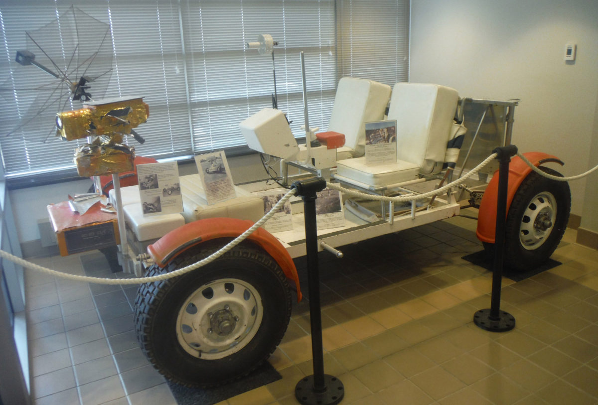
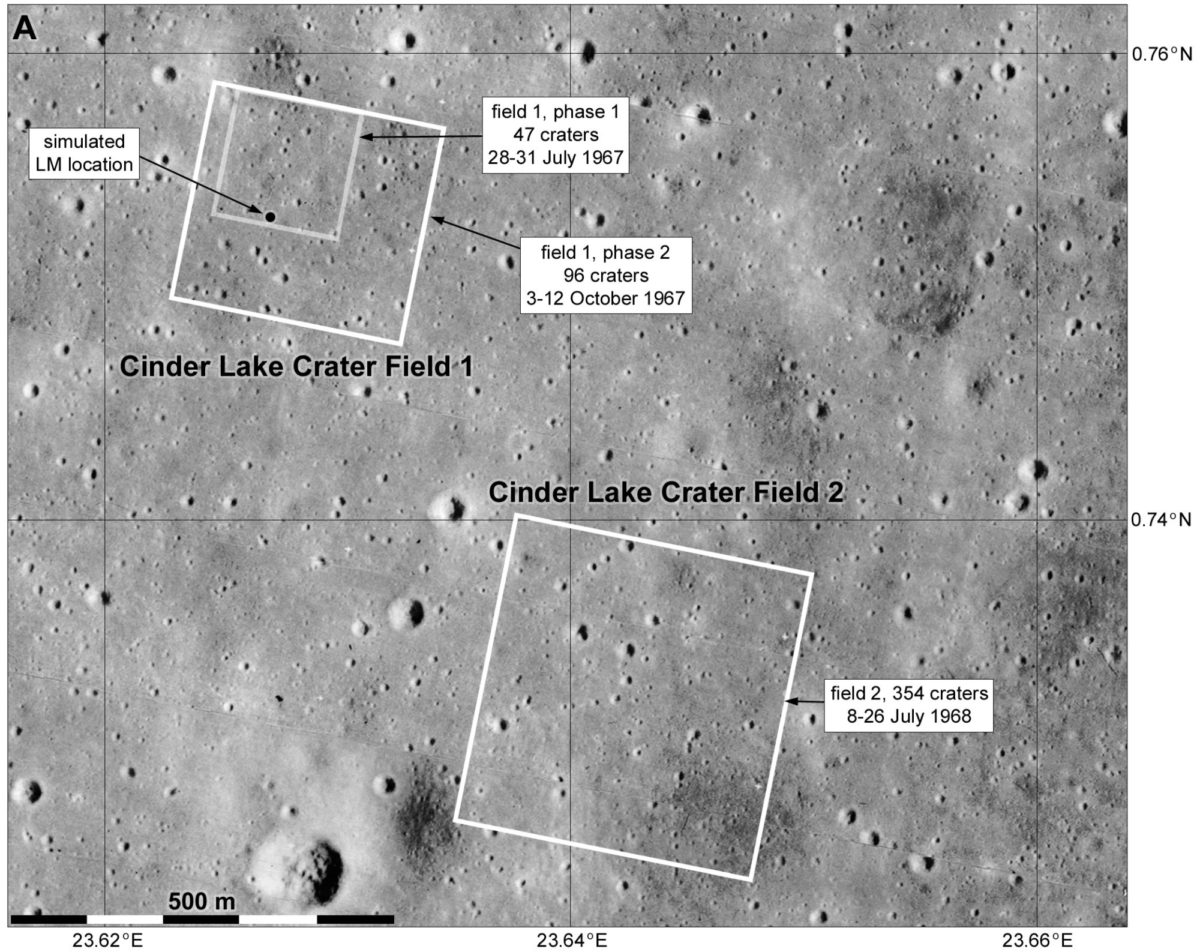
One of the places Grover was driven was Cinder Lake, a flat area of volcanic ash northeast of Flagstaff. In July 1967 the USGS set about modelling part of Apollo Landing Site 2 in Mare Tranquillitatis at 1:1 scale at Cinder Lake, basing their efforts on a Lunar Orbiter 2 image. First they set off measured amounts of explosives to calibrate a method of excavating craters of different sizes. Then, using the image as a guide, they set off a series of explosions to dig craters of roughly the size and arrangement seen on the Moon. That area was not big enough, so they enlarged it in October 1967. The geologists were mapping the landing sites, trying to understand how crater ejecta blankets overlapped, and the astronauts would be looking for signs of ejecta layering, but the artificial crater field was not very suitable for this. A new crater field was constructed nearby where volcanic ash lay over clay, and three separate sets of explosions produced overlapping ejecta deposits which would be easier to interpret. That was done in July 1968, again based on an image of part of the actual landing site. The crater fields are still there at Cinder Lake, a bit degraded by weather and off-road vehicles, and by comparing them with Lunar Orbiter images I have located the areas of the Moon which were modelled at Cinder Lake.
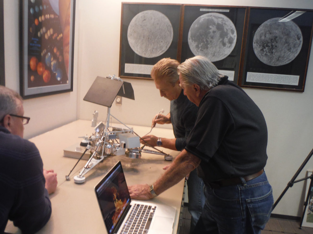
The RPIF in Flagstaff is now run by David Portree, who welcomed me warmly and helped me find some useful things. I went through lots of archive boxes and had some items copied. More of that later. But another very unexpected pleasure was meeting Justin Rennilson and his son Gary, who had been working on the recovery of Surveyor images, as just described by Jason Davis. They were in Flagstaff to photograph a sub-scale model of Surveyor. The newly scanned negatives will allow exciting new work on the Surveyor sites, never before seen views of the landing sites under many different lighting conditions, and movies of robotic arm operations and lengthening shadows, etc. I certainly encourage anybody with an interest in space image processing to get into the images when they are made available.
Now for a couple of things I found in the archives. The first concerns the backup landing site for Apollo 12. Apollo 11 only had to land safely and get back home, and if it was 5 kilometers off-target, nobody would object. In fact they were a bit more than 5 kilometers away from the middle of their landing ellipse, but it really didn’t matter. But a sophisticated lunar exploration program would need more accuracy, so that the crew could walk to specific pre-planned points of scientific interest.
A pin-point landing (within walking distance of the target) was a major operational goal for Apollo 12, so what was the target going to be? There were two main candidates, a landed Surveyor spacecraft or a small fresh crater which had sampled bedrock under the regolith. The Apollo Site Selection Board (ASSB) and the Group for Lunar Exploration Planning (GLEP) went back and forth over the choice and eventually decided on a Surveyor, and of two possible choices in the broad region they wanted to land in, Surveyor 3 was preferred over Surveyor 1. Sure enough, that’s where Apollo 12 landed.
But this is not the whole story. The early Apollo missions had not just a preferred landing site, but also a backup site in case the launch was delayed. The crew had to be able to see subtle relief features as they landed, to be sure the site was safe, and it helped if the sun was very low in the sky and casting long shadows. If the launch was delayed a couple of days (the minimum time to prepare a new launch), the sun would have risen too high over the prime landing site and a new one further west would be needed. Apollo 12’s backup site in Oceanus Procellarum was called Site 5 (there wasn’t anything very interesting nearby to name it after), but that was a big landing ellipse, not a specific point. There was no Surveyor at Site 5, so a small fresh crater would have to be the target.
I thought I knew this story, and told what I knew in my old Atlas. Newell Trask of the U.S. Geological Survey in Menlo Park, CA was asked to identify targets and did so, providing a list to James Sasser of NASA’s Manned Spacecraft Center (now the Johnson Space Center near Houston). GLEP chose one and recommended it to ASSB, who then proposed it to the Apollo Program managers. Don Wilhelms tells this story in his book, but doesn’t identify the sites or the final target. I managed to find a memo from GLEP to ASSB with their recommendation in it, and that made it into my book. But even that was not the whole story.
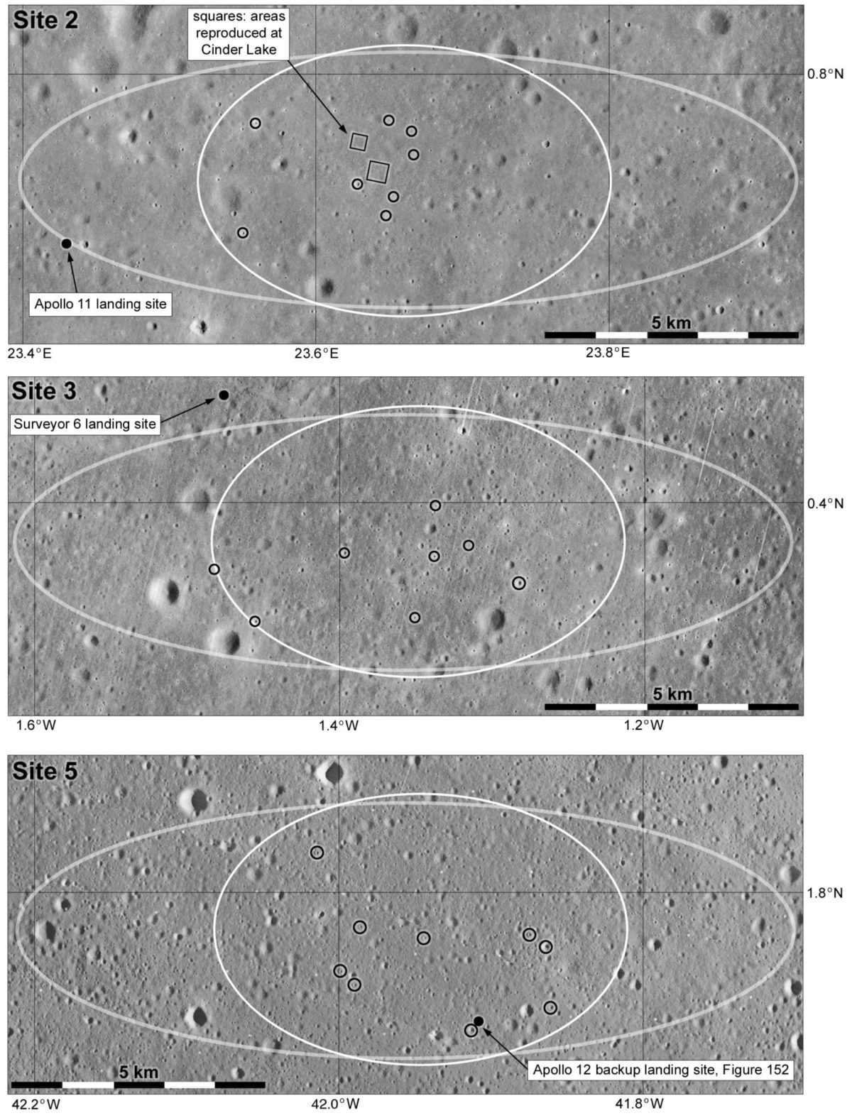
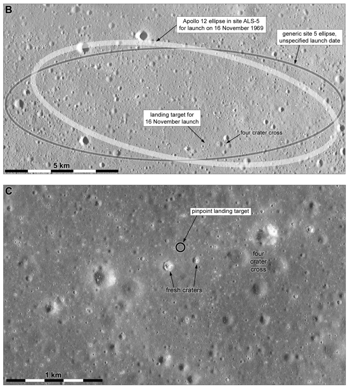
Flagstaff to the rescue! Here I found Trask’s original memo to Sasser. To my surprise it was dated before Apollo 11, not after it, and it did not just cover Site 5. Trask was working on this in the weeks leading up to the launch of Apollo 11, and even though that mission was targeted at Site 2 in Mare Tranquillitatis, there was no certainty it would land there. Launch delays could push it to Site 3 in Sinus Medii or Site 5 further west again. So the second landing might be directed to any of those sites which Apollo 11 did not land at, possibly including Site 2. Trask identified 8 fresh craters in Site 2, 8 in Site 3 and 9 in Site 5, and he sent the memo to Sasser on June 19, 1969, a month before Apollo 11’s landing on the Moon. When Apollo 11 landed at Site 2, Apollo 12 was targeted at Surveyor 3 (which was called Site 7) and only Site 5 would work as a backup. One of Trask’s locations in Site 5 had not one but two small fresh craters, and another big advantage was a distinctive pattern of four larger craters called ‘Four Crater Cross’, which would be easy to spot on the approach to help the crew guide the LM down to the landing site.
There was only one problem with all of this. Trask’s target points were identified as measurements in centimeters on Lunar Orbiter images, not by latitude and longitude. Luckily, these images were usually printed at a standard size, and knowing that I could use scans of the Lunar Orbiter images from the Lunar and Planetary Institute website to find the locations. Figure 5 shows the pinpoint landing targets at all three Apollo sites, and Figure 6 shows the actual backup Apollo 12 site.
Now let’s go from the early landings to the last, Apollo 17. It carried Gene Cernan and Jack Schmitt to the Taurus-Littrow Valley, but there were several other potential targets for the last landing, and the most dramatic was the farside crater Tsiolkovsky. Schmitt pushed hard for that site but it was too difficult, and there was no extra money for a communication relay which would be essential for a farside landing. One scheme was to use a military communication satellite, one of a group which were being built at the time for the Department of Defense. Apart from those slated for launch, there were to be two spares, built and put into storage for later use in the event of an on-orbit failure. One of those might be used for Apollo 17. It would be placed in a loose halo orbit around the Earth-Moon Lagrangian point L2, above the lunar farside, from which it would be able to relay transmissions from the landed spacecraft directly to Earth. But it would need modifications, and the money was not available. Now, more than 4 decades later, the same idea is being planned by China for a farside lander and rover, the Chang’E 4 mission, in 2018, and probably for a later sample return mission.
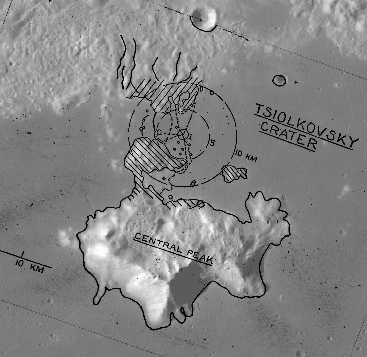
But if you are going to Tsiolkovsky, where would you land and what traverses might you undertake? I had never seen the planned surface traverses until this visit to Flagstaff, but they showed up in a presentation on the communication satellite plan. Figure 7 shows the planned Apollo 17 traverses superimposed on an LRO wide angle mosaic. The landing site would be just north of the central peaks, with traverses to the base of the peaks, and to the hilly terrain north of the landing site, probably consisting of material which has slumped down from the crater walls. The other major sampling target would be the dark basalt plains on which the Lunar Module would land. This same site was one of the locations considered for a Constellation sortie mission before that program was cancelled.
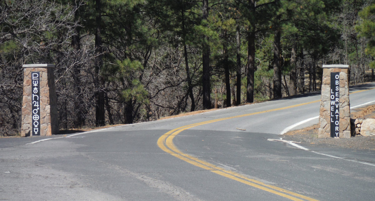
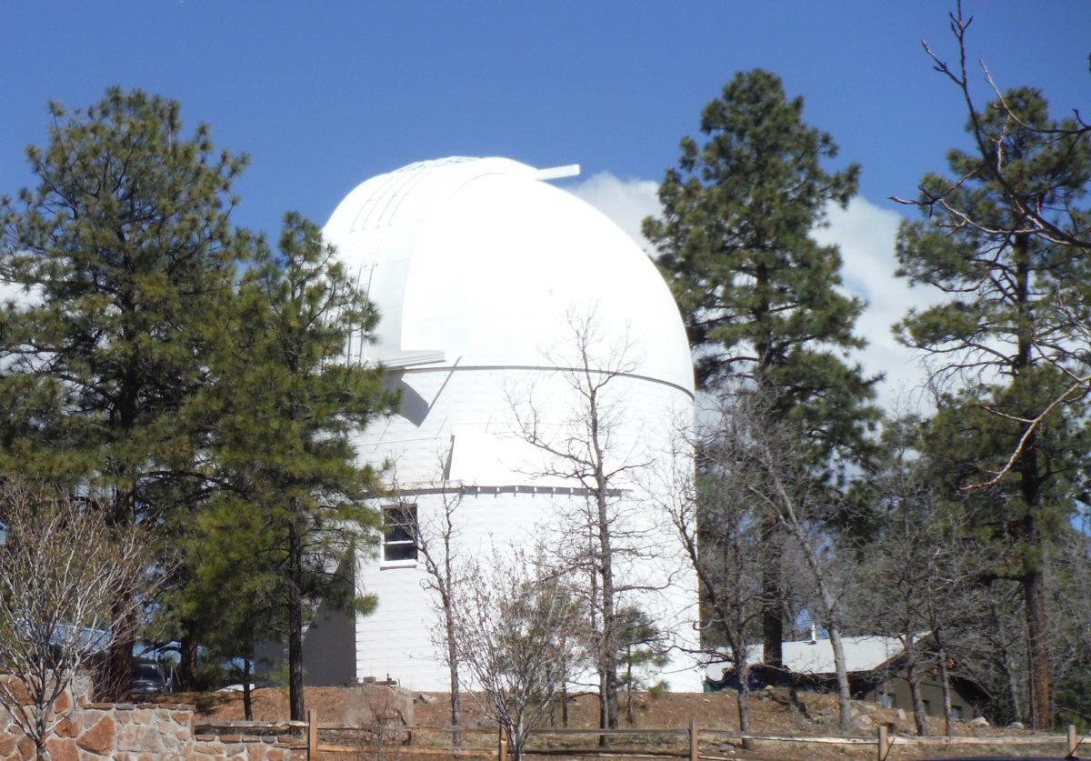
No trip to Flagstaff would be complete without a visit to Lowell Observatory, on a hill west of the downtown area. This venerable institution is where Clyde Tombaugh discovered the plan- uh – I mean Pluto in 1930. Sure enough, the Visitor Center was sporting a banner proclaiming it as ‘The Home of Pluto’, and the observatory entrance displays the symbols of all nine planets, as they were thought of for so long. Pluto may have been demoted, but its symbol still rides high at the top of its pillar. Up on the hill a blue sky backed a gorgeous view of one of the telescope domes. Flagstaff is a great place for a space fan to visit, and a beautiful little town for everyone else.
Let’s Go Beyond The Horizon
Every success in space exploration is the result of the community of space enthusiasts, like you, who believe it is important. You can help usher in the next great era of space exploration with your gift today.
Donate Today

 Explore Worlds
 Find Life
 Defend Earth