Mike Blackstone • Jul 12, 2018
Generation Zero of JPL Planetary Rovers
Introduction and Mission
The Jet Propulsion Laboratory (JPL) has a fabled history of planetary rovers. But how do you start such a program? In 1972, I participated in the first small effort to bootstrap JPL's rover program. Dr. Ewald Heer oversaw a project to assemble a proof-of-concept rover from existing components, film a demo of the rover operating in a simulated planetary surface, and use the demo to sell the idea to funding authorities. Since this project came before the first generation of "real" rovers at JPL, I like to call it Generation Zero. Unfortunately, I have practically no documentation from the project; everything here is based on my memory.
My first real job was as a contractor programmer working at JPL. My second assignment was to Dr. Heer's project, based on my grasp of trigonometry! Dr. Heer had collected the bootstraps of his project from existing resources at JPL. He had a staff engineer, whose name I recall as “Joe.” He had a large room in one of JPL’s buildings. He had a computer. He had a contract programmer. And, most important, he had a robot!
The "mission objective" was to place a rover on a simulated planetary surface, have it survey its environment, allow "mission control" to designate a target of interest in the environment, command the rover to drive to the target, allow the controller to verify the suitability of the target, and grasp the target for close visual examination.
Mechanics
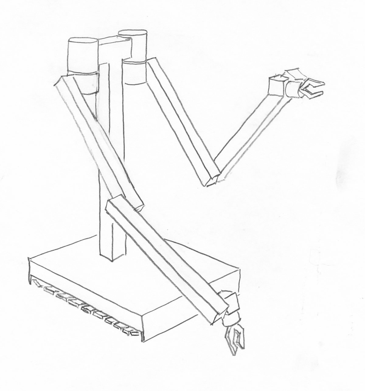
The "robot" was originally a teleoperated manipulator. (I call it a robot for brevity.) This means that it did nothing on its own, but was controlled remotely by a human operator. JPL had used it to handle dangerous chemicals for developing rocket fuels. This activity occasionally resulted in explosions, so the robot had to be very rugged. It was manually controlled from a panel of knobs. The operator could sit in a blockhouse, protected from potential blasts. The diagrams show a sketch of the robot as I first saw it, and the manual control panel.
The control panel had a knob for each arm joint, gripper, and track drive. Turning the knobs controlled the direction and speed of the motors. To stop motion of a joint, the operator had to center the knob. In the sketch, the track controls are set to pivot the robot to the right: the left track moves forward and the right track moves backward. Manipulating explosive chemical mixtures with this system must have been challenging!
Mobility
Mobility was provided by two tank-like tread drives under a rectangular base, well shielded from potential explosions. A connector at the back of the base accepted a long, thick cable for power and control signals from the panel. The mobile base supported a T-shaped post, supporting two hefty shoulder cylinders.
Arms and Grippers
The teleoperator stood about five feet high at the shoulders. Each of its arms had a shoulder sideways rotation joint, a shoulder elevation joint, an elbow joint, a wrist elevation joint, a hand rotation joint and a two-fingered gripper. All the motors were in the upper part of the shoulder cylinder. Below each shoulder, the joints were actuated by chain drives (like a small bicycle chain) that ran within the hollow segments of the arm.
The gripper was actuated by hydraulic pressure. Everything from the shoulder to the wrist was hollow, sealed, and filled with hydraulic fluid. The whole thing was painted a light industrial green, except for the joints, which were stainless steel. The arms were long enough to reach the ground in front of the base.
Sensors
As a teleoperator, it had no sensors. Joe developed circuitry to measure the robot's joint positions by potentiometers he attached externally (not shown in these diagrams).
Joints
As a joint moved, the changing resistance of the potentiometer varied a voltage that indicated the position of the joint. The voltage signals from all of the potentiometers were run through a multi-channel Digital-Analog converter and other circuitry that turned each voltage into a number that could be read by the computer’s input/output system. From the point of view of the computer, the state of the robot’s joints was a list of numbers, one for each joint.
Video
The teleoperator had no video capability; it relied on the operator’s ability to see the robot and its surroundings, either directly or through a periscope in a blockhouse. To provide for visual inspection and depth perception, Joe added a new subsystem to the top of the support post. This consisted of a pan-tilt head, driven by the same kind of circuits as the arm joints. At the top of this was a beam with two identical vidicon tube TV cameras. The two cameras were mounted with their optical axes parallel, and at right angles to the beam, spaced about two feet apart. When its “eyes” were installed, the robot was nearly six feet tall.
The monochrome video signals were sent to two monitors for the human operator to view. Each monitor had a set of crosshairs superimposed on the screen over the video image, controlled by two three-digit sets of thumbwheels below each screen. The operator adjusted the thumbwheels so that the crosshairs were over a target on each monitor. The computer could not read the thumbwheels; I had to type their values at the computer console. The crosshair positions were easily converted to angles in the video system frame of reference.
Control
From the computer’s point of view, the robot’s commanded joint positions (including the pan-tilt head and tracks) were simply a list of numbers, sent to the control circuitry. To control each joint, Joe devised a circuit that accepted the commanded position value from the computer, compared it with the value of the joint’s sensor, and generated a drive voltage for the joint’s motor based on the difference. He designed the circuit so the drive voltage was constant for large differences, but as the joint neared the commanded position, the drive voltage declined until it reached zero when they coincided. In this way, large movements could be reasonably fast, and yet the joint wouldn’t overshoot its commanded position (usually).
All of the new circuitry was housed in a box mounted on the robot’s base, behind the main post. A useful feature of the modifications was that they did not disable the use of the original teleoperator control panel; either that panel or the new electronics package could be connected to the robot.
Integration
Integration of the system components took place in the same space as the demo. A new wall divided the space into two parts: the simulated planetary surface and mission control. For convenience during development, the controller could watch the rover through a large picture window.
Processing
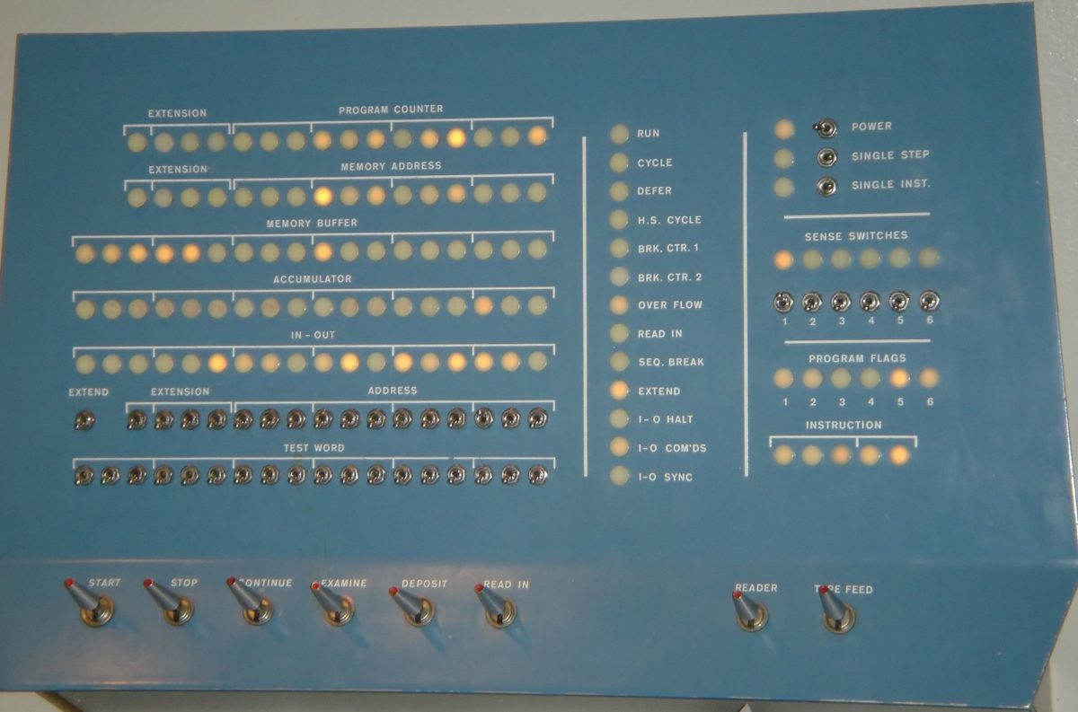
Processing power for the rover was a Digital Equipment Corporation (DEC) Programmed Data Processor 1 (PDP-1). This was an innovative computer when it was designed in 1959, but the rapid development of computers over 13 years had made it practically obsolete. DEC made about 55; the one we used was serial number 13. You can find more detail about the PDP-1 at the Computer History Museum. (I obtained the pictures below from their website) The PDP-1 occupied four refrigerator-sized cabinets, and had an operator's console with 119 lights to show the state of the computer, 44 small switches to enter bits into registers, and eight big action switches at the bottom.
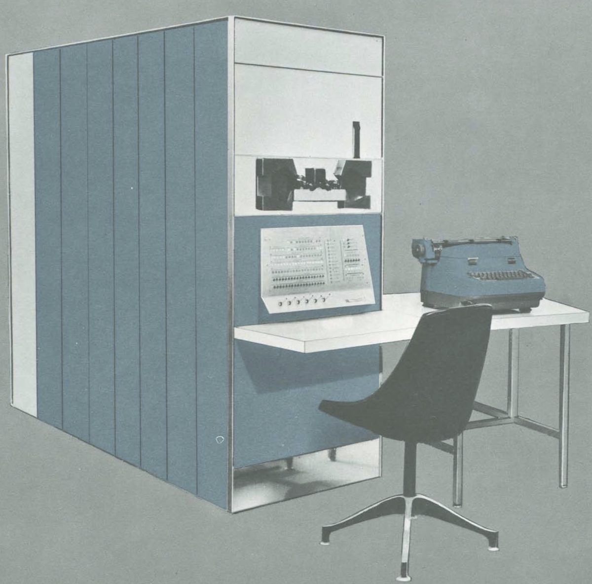
Working on this computer, the programmer deals directly with the 0’s and 1’s (binary digits, or bits) that underlie all digital computers. The small switches on the console correspond to 0 when down and 1 when up; the lights are on for 1 and off for 0. Nowadays we might say this is working “close to the metal.” In those days it was not unusual.
The PDP-1 came with a wicker basket of paper tapes containing some utility routines, including floating-point arithmetic and trig functions. Using these, I developed a set of modules that could:
- Read the rover's joint configurations and calculate the position of its grippers, as well as the orientation of the video system
- Use the thumbwheel switch values of the video subsystem to determine angles to a target in the video frame of reference, and calculate the coordinates of a target in the rover's frame of reference
- Use the target's coordinates in the rover's frame of reference to calculate the joint angles to place a gripper at the target
- Command the rover's drive tracks, joints, and video system to the desired positions
The software was developed as a modular set of routines for the basic functions, and could be invoked individually or in pre-defined sequences by single-letter commands entered at the PDP-1's typewriter. The thumbwheel values were also entered on the typewriter.
Demo
The project's objective was to execute and film a demonstration of the feasibility of remotely controlling a robot on the surface of a planet, such as Mars.
We developed a demo sequence starting with the rover standing near a field of small rocks. (These came from a Hollywood prop supply company; they were foam rubber with a slightly stiff gray faceted surface that created reflective highlights as they were moved under the overhead lights. The rocks were in a variety of sizes and shapes, a few inches across. The robot’s grippers could open up to five or six inches, and easily accommodated them.) The rover first panned the video system across the area, then paused while the operator selected a target rock. On command, it then drove to the selected target and paused again while the operator refined the target's position. On further commands, it moved a gripper over the target, picked up the rock, and finally raised it for observation by both cameras, while it continuously rotated its gripper.
After two or three months of development, with very light supervision, the demo was ready. A cameraman came in and filmed a few run-throughs of the demo, from different angles. I never actually saw the film. However, I have modeled the rover as I recall it, and produced an animation showing how the demo worked. You can view it on Vimeo. The picture below is a frame from that video, showing the rover after picking up a rock.
Mission Accomplished!
The demo must have been well received, judging from subsequent rover developments. A mere 25 years later, the rover Sojourner rolled onto the surface of Mars. However, I moved on to other assignments and had no further involvement with JPL's robotics program. Looking back, it was my best job ever.
This article is just a summary of my story of working on Generation Zero. You can read the whole story here. By the way, if anyone reading this has information about any artifacts from this project, I would love to know about them.
Let’s Go Beyond The Horizon
Every success in space exploration is the result of the community of space enthusiasts, like you, who believe it is important. You can help usher in the next great era of space exploration with your gift today.
Donate Today

 Explore Worlds
 Find Life
 Defend Earth
