Emily Lakdawalla • Nov 08, 2011
How radio telescopes get "images" of asteroids
This is a repost of an article I wrote in April 2010; I thought it'd be useful reading for those of you interested in today's near-Earth flyby of asteroid 2005 YU55.
Every time I post a radio telescope image of a near-Earth asteroid, I get at least one reader question asking me to explain how radio telescopes take photos, so I'm hereby writing a post explaining the basics of how delay-Doppler imaging works.
To begin with, imaging of any kind done with radio telescopes (or radio antennae on spacecraft) is an active technique: the imaging requires that the antenna first broadcast a signal at the object of interest. The signal reflects from the object, and the antenna waits for the return signal.
The simplest sort of radio "imaging," then, is just radio ranging. Send out a ping, wait for the echo. Use a precise clock to time how long it takes the reflection to return to the antenna, and you know very precisely the range or distance to the target. That's RADAR, which is an acronym for Radio Detection and Ranging.
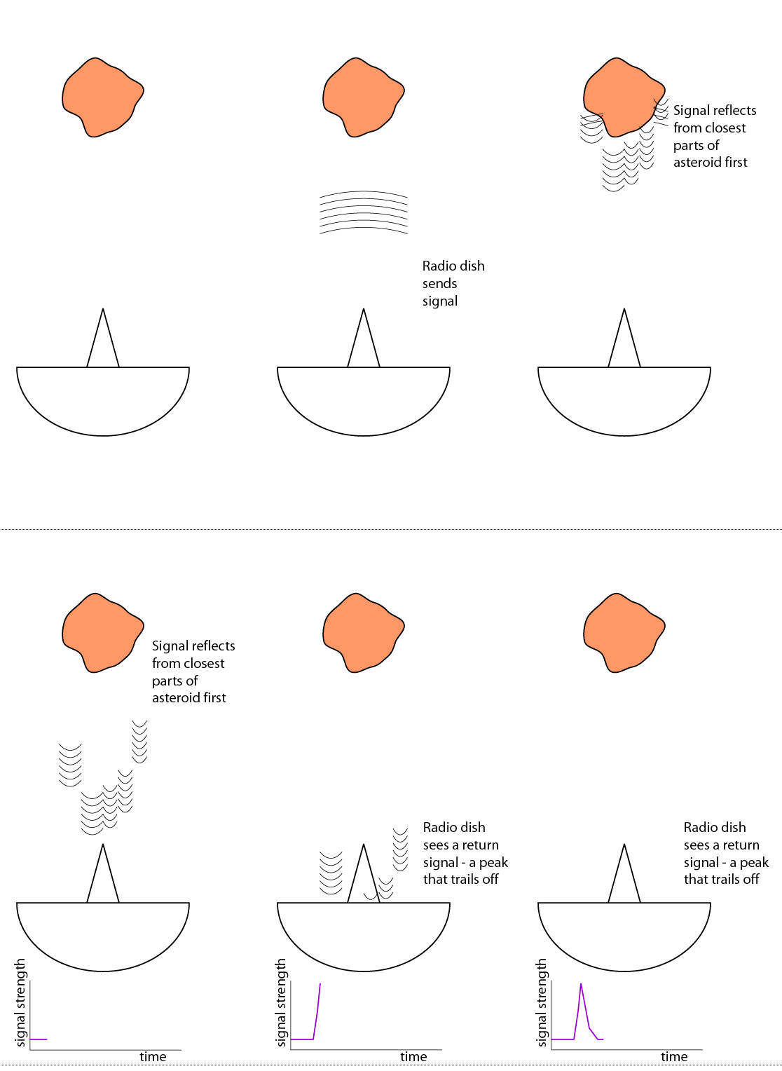
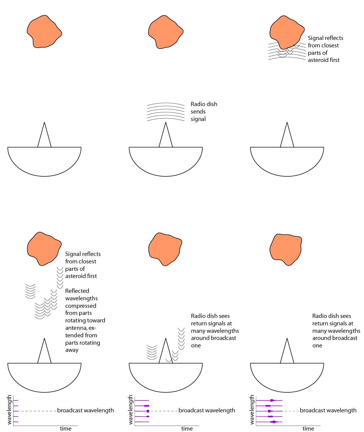
But we can do better than that. Here's a very simple cartoon that I drew, grossly simplifying what happens when you broadcast a signal at a lumpy object.The signal goes out as a nice waveform. It's reflected from the parts of the asteroid that are closest to the radio dish first, but while those first reflections are happening, the radio wave is still propagating toward more distant parts of the asteroid. So when the radio dish detects the return signal, the sharp signal has been spread out in time.
You can see how you could use these data to crudely estimate the size of the object you were looking at. The first reflection comes from the nearest parts of the object. The last reflections come from the most distant parts of the object that you can see. Take the amount of time that separates the first and last reflections, multiply it by the speed of light, and you get the distance between those two points. Then double that, assuming the body is quasi-spherical and has a hidden hemisphere behind the hemisphere we can see. This will not be a particularly accurate estimate, but it's a start.
One thing we can't do is figure out which reflections were coming from which parts of the asteroid. All we know is how strong the return signal was with respect to time.
Radio imaging gets better, though. It takes advantage of the fact that everything in the whole solar system is rotating. Some things rotate pretty fast. Imagine a set of waves propagating toward a rotating body. Actually you don't have to imagine it, I've drawn another horribly oversimplified cartoon.
As an asteroid rotates, some parts of it are moving toward us, while other parts are moving away. As the broadcast radio wavefronts hit the part of the asteroid that is moving toward us, the asteroid smacks into each wavefront faster than it would if it were not rotating. The speed of the wavefronts does not change, because the speed of light is constant, so the wavefronts end up being packed closer together. This is a Doppler shift. The asteroid has taken the broadcast wavelength and reflected it at a shorter wavelength from the parts of the asteroid that are rotating toward us. On the other side of the asteroid, which is rotating away, the opposite thing happens; each arriving wavefront smacks into the asteroid a little later than it would if the asteroid were not rotating, so the reflected waves are spread farther apart.
(One minor point here: the asteroid is not only rotating, it is also moving at some high speed with respect to Earth. So the whole return signal is already going to be Doppler shifted in one direction or the other depending on whether the asteroid is coming at us or going away from us; radio scientists account for this and "look" for the reflection around the expected return frequency given this Doppler shift due to the asteroid's motion. The Doppler shift due to the asteroid's rotation is a small increment of shift on top of the shift due to the asteroid's motion.)
Back at the radio dish, we have a detector that can split the incoming reflected waves into its different wavelengths. (Much like color cameras split incoming light into their different wavelengths.) The radio dish records the time and strength of the return signal at many different wavelengths. The result, as you can see in the crude graph at the bottom of the animation, is a "picture," actually a sort of colored-in graph with time on one axis and wavelength on the other axis. The faster the object is rotating, the more Doppler-shifted the return signals are; fast rotators spread out more across the wavelength axis. Things that aren't rotating at all, like in my first animation, collapse into a blip at the central wavelength.
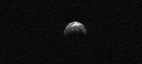
Radio scientists refer to time as "delay," as in "the delay between our broadcast and when we heard the return signal," and the wavelength axis of my crude graph above as "Doppler." So turn that graph on its side and you get an explanation of how radio scientists can arrive at an image like this one, the significance of which I will explain in the next post. Arecibo would be two million kilometers above your head; delay increases from top to bottom, Doppler from left to right.
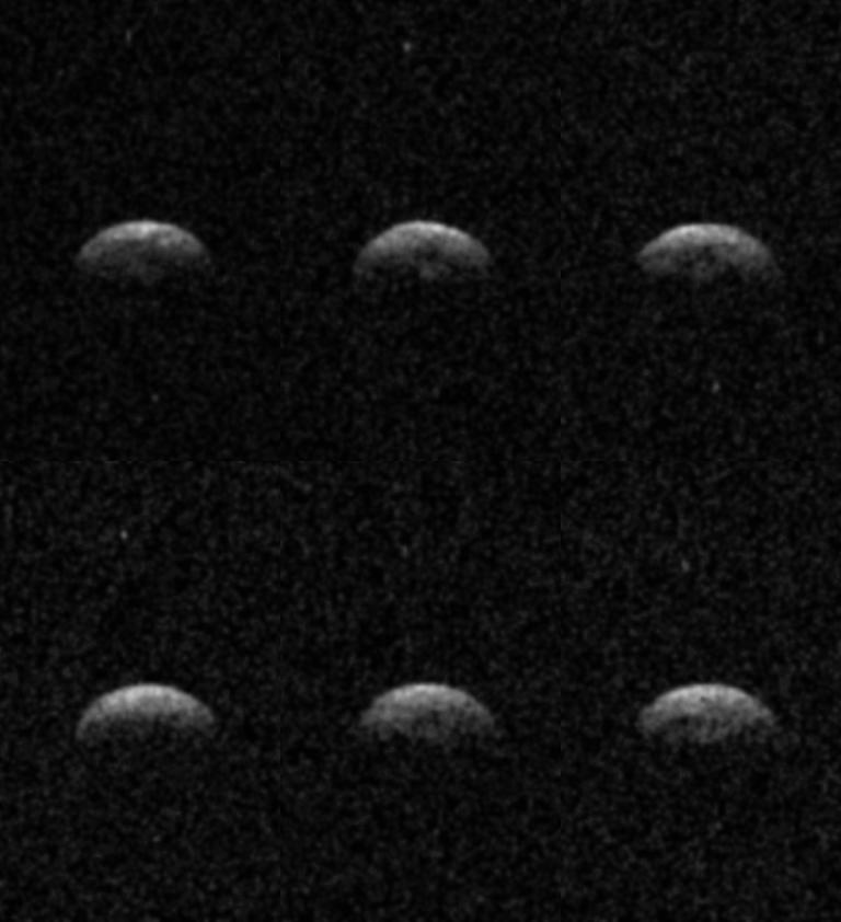
But this is one of my favorite delay-Doppler observations, an animation:
Let’s Go Beyond The Horizon
Every success in space exploration is the result of the community of space enthusiasts, like you, who believe it is important. You can help usher in the next great era of space exploration with your gift today.
Donate Today

 Explore Worlds
 Find Life
 Defend Earth